-part 3-
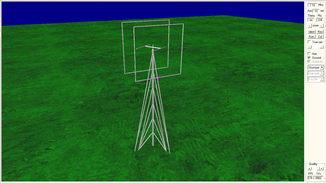
In the previous part, we talked about vertical antenna for 15 m band, while in the first part, we talked about 40 m band. Not so consistent isn’t it ? Well, let’s convert our 15 m band vertical antenna for 40 m band operation.
Actually, converting/resizing an antenna for another band is pretty straightforward, especially if the band of interest is not so far away from the previous band (relatively speaking). In fact, if we have some antenna size which is intended for 160 m band, we can easily resize it into the proper size for 10 m band, without many correction afterward. To resize our antenna for another band, we rely on a fact that is the size of the antenna elements is linearly proportional to the wavelength. Which means that if we have an antenna element that is, let say, quarter wavelength long, the new length for another frequency is must be quarter wavelength long as well (new frequency wavelength). It is so basic that I believe you already do know about it, but you will be surprised that how many amateur radio who don’t.
The paragraph above actually can be simplified into one formula as follows :
new_size = old_size x (old_freq / new_freq)
That’s it. Well, actually not. The proper formula is as follows :
new_size = old_size x (old_freq / new_freq) x corr_factor
With corr_factor is a correction factor, which largely depends on how much logarithmic distance between new and old frequency. For now, let assume that corr_factor is 1. This formula is can be applied and must be applied to everything. If you resize the vertical radiator element then you have to do it for radials as well, as well as your wire size, the height above the ground, the size of alu. tube you are using (if you are building a rotary dipole, for example), the elements spacing (in the array antenna case), even your boom size, everything ! In many cases, you cannot resize the diameter of wire or tube you are using. In that case, corr_factor comes into calculation, but practically it is still very close to 1.
I’ve been using this technique last year when I built my 1 element diamond loop antenna for 15 m band. At that time, first I simulate and built diamond loop for 4 m band (to verify the dielectric constant/material of the wire insulation i’ve been using, turns out it was soft PVC), I optimized it for soft PVC material and then I resize it for 15 m band as accurately as possible. The first time I built it for 15 m band, it was perfectly matched exactly at the frequency that i wanted (it was 21,05 MHz for CW / Digital operations). No tuning required. At first night I even got a nice EU pileup with it on CW.
Some Examples
Now we will try to resize/calculate the proper size of the 15 m band vertical antenna above seawater (last article) into another bands, 160 m to 10 m. Let’s recall our last antenna dimensions.

We will use some notations as follows :
A = vertical radiator length = 3,9 m
R = radials length = 2,34 m
H = height above ground (seawater) = 1 m
D = wire dimensions = 1,6 mm dia. copper, 3,8 mm dia. soft PVC insulation.
new_size = old_size x (old_freq / new_freq) x corr_factor
With some simple calculations on a spreadsheet, we get new antenna dimensions as follows :

Then under 4NEC2 we can predict the VSWR value of the new antenna dimensions on each band. The results is as follows :

Wow, the new antenna dimensions on each band virtually has identical VSWR value as reference antenna has. Then it’s done right ? Well, no. Actually we have some problems here. First, we have some unpractical wire size (D) for the antenna element due to resizing of the D dimension into new frequency. Second, the height of the vertical antenna base above ground level (H) is uncomfortably high for practical purpose. You can see on the first table that H dimension for 160 m, 80 m, and 40 m is too high. This is due to resizing of H dimension into new frequency. The two problems above shown in the highlighted table bellow :

To attack this problems, we can set the physical limitations into our design and using various corr_factor to resize our dimensions on each band. In this article we set the physical limitation of H is 2 meters maximum (2.08 m value for 30 m band is close enough so we don’t bother to recalculate this) and same wire dimension D for all band. Next we can optimize the required corr_factor for each band using optimization tool in 4NEC2.

As it turns out, after we recalculate the proper size of each elements for each band and applied the correction factors needed due to physical limitations we set before, it is still very close to the initial dimensions. Very nice !
Conclusion
A method to resizing an antenna dimensions from one band to another is presented. Due to physical limitation, sometimes we can’t resize all dimensions properly, hence we need to apply correction factor into calculations. The results is the correction factors value is very close to 1 at the entire HF band and the final dimensions is still very close to the initial.
73, Handiko
YBDXC #193
source link
 YB Land DX Club DX-ing Is Our Life


