http://www.leoshoemaker.com/files/HEXBeam_by_K4KIO.pdf
HEX BEAM
Step 3: The Center post
• The center post is for mounting the terminals that connect the various bands’ driver wires to the coax feed line. It is made of basic one inch PVC plumbing that is a perfect fit into the baseplate described in Step 1.
• The terminals are located on the center post and are European terminals. The terminals are connected with 50 ohm coax pieces from the bottom terminals to the top where they are connected to the feedline from the transceiver.
• All bands are connected together via the coax links and are all fed by a single feedline.
• The terminal spacing on the center post and the length of the post itself are set forth below along with steps for constructing the center post.
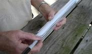
A vertical line to mark the holes for the European style terminals should be marked. The post should be 40 inches long and locations for the Euro terminal mounting holes should be marked as shown to the right.
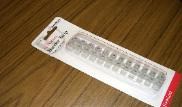
These jumbo size European style terminal strips at Radio Shack can be easily cut into 6 double terminals to attach to the center post. The jumbo size is needed to accommodate the coax and the wires that must be inserted into the terminals. These can be obtained from other vendors such as Mouser
Drill a hole completely through the post for each terminal at the marks made in the first photo. You will be using a #6-32 X 2 brass or stainless steel bolt for each terminal. The bit size should be
9/64 inch. Install a double European terminal for each band at the marks.
See more details:
Here is schematically what you will be doing with the terminals on the center post. Only five bands are shown here but the sixth can be added below 10 meters. Be careful not to flip one of the coax pieces so as to put its shield on the side of the inner conductor of the others. It will cause big problems in performance.
Also, why not do a simple test for shorts when you get this finished? A piece of braid touching the inner conductor would be a headache to avoid with such a simple test.
See more details:
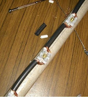
Cut coax pieces for connection between the center post driver terminals. If you are not going to be running more than 500 watts of transmitter power output, you can use RG 58 coax instead of RG 213 and it is much easier to work with.
Seal up the exposed coax braid with liquid tape or silicone sealant to keep moisture out. Apply it also to the metal of the terminals as the metal is steel and will rust if not protected. Paint has been applied. The driver wires will be bent to an “L” shape on the ends and pushed down into the tops of the terminals. Add a 1/2 inch to each driver half wire in Step 4.The feed line will also be connect to the top terminal and looped down the side of the post to the bottom of the hex beam.
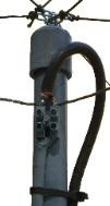
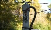
Here is how your coax connects to the top of the center post to feed all the bands. Of course, you need to seal it up with liquid tape or silicone to prevent moisture from entering the braid and contaminating it. The wires are shown installed here as well as the radial cords. Use an eyebolt through the cap on top to anchor all the radial cords.
 YB Land DX Club DX-ing Is Our Life

